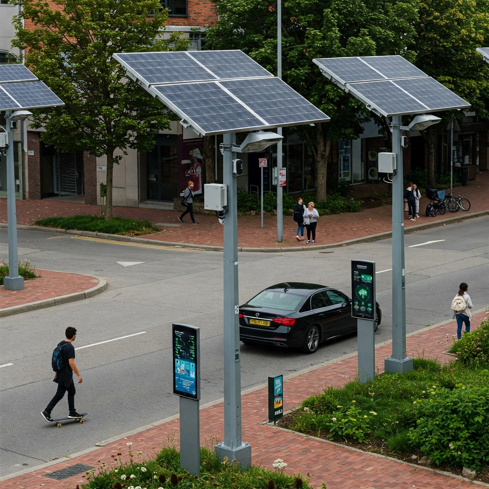



A solar street light in the Philippines is not mainly a lighting purchase. It is street furniture that has to survive around twenty tropical cyclones in a typical season, plus the ordinary gust front of almost every afternoon thunderstorm. When a unit fails in year two, the LED has usually not degraded. A bracket weld has cracked, a clamp has rotated, an anchor bolt has pulled out of a pad, or water has found a path into the battery compartment.
This guide covers the mechanical side of the specification: how wind load is turned into a number, which pole and mounting parameters actually carry that load, and what to send a supplier so the quotation covers what your site will do to the installation. It deliberately does not quote a wind resistance figure for any particular fixture, because that figure means nothing in isolation. It depends on the pole, the bracket, the foundation and the exposure of the site, and it has to come out of a calculation rather than a catalog page.
Wind Does Not Break the LED, It Breaks the Interface
Wind pressure becomes force only when it meets an area. The larger the surface being pushed, the larger the load transferred into every fixing between the module and the ground. An all-in-one solar street light puts three high-area elements on one arm: the photovoltaic module, the luminaire body and the battery housing. A split system separates the module from the luminaire, but the module often sits higher, where wind speed is greater.
The load path runs module to bracket, bracket to arm, arm to pole, pole to base plate, base plate to anchor bolts, anchor bolts to foundation. Every joint in that chain is a candidate failure point, and the cheapest joints in a bill of materials are the ones that fail first: a spot-welded bracket instead of a continuous weld, a single clamp bolt instead of a two-bolt clamp with an anti-rotation pin, an anchor bolt too short for the pad it was cast into.
This is why two suppliers can both ship a “typhoon-ready” light and only one still stands after a Category 3 crossing. The claim is not the specification. The drawing and the torque value are.
Start From the Basic Wind Speed, Not From a Pole Catalog
Wind design in the Philippines follows the wind provisions of the National Structural Code, which are built on the ASCE 7 approach. Your structural engineer takes the basic wind speed for the site, adjusts it for exposure category, height above grade and topography, and arrives at a design velocity pressure. The standard forms are:
q = 0.613 x Kz x Kzt x Kd x V² q in N/m², V in m/s, with Kz the height factor, Kzt the topographic factor and Kd the directionality factor.
F = q x Cd x A F in newtons, Cd the shape coefficient, A the projected area in square meters for the worst wind direction.
Three consequences follow, and all three are procurement decisions rather than engineering trivia. First, V is squared, so a site with a higher basic wind speed does not need a slightly stronger pole, it needs a disproportionately stronger one. Second, Kz increases with height, so a taller mounting height is not just a longer pole, it is a pole carrying a larger design pressure. Third, A covers everything the wind sees on the arm, module included, at the direction that produces the worst case.
That is the calculation you should be buying. Ask every bidder for the pole schedule and the foundation drawing their quotation assumes, then hand both to your engineer together with the site basic wind speed. A supplier who cannot produce a pole schedule is selling a lamp, not a street lighting installation.
Projected Area: Where Solar Differs From Ordinary Street Lighting
A conventional LED street light presents a slim housing to the wind. A solar unit presents a module tilted toward the equator, which also presents area to wind arriving from the front, and its centre of pressure sits above and often forward of the pole axis. The result is bending combined with torsion that a standard street light pole was never detailed for.
These details reduce the load without touching light output:
- Module position: bolting the module close to and over the battery housing shortens the lever arm compared with a long forward-tilted bracket. On a split solar street light the module and the luminaire are separate bodies, so the mounting frame, not just the pole, becomes the critical part.
- Bracket geometry: a continuous welded gusset spreading the load over a length of the arm behaves very differently from a single tube welded to a plate at one point. Weld quality at that joint decides whether the arm stays square after ten storm seasons.
- Frame and fixings: a continuous extruded frame with through-bolts at the four corners of the laminate holds the glass under gust loading; a thin folded sheet frame flexes and eventually cracks it.
- Orientation: do not assume the prevailing wind direction is the design direction. The worst sector for a site is a question for the engineer, and it is often not the direction the light faces.
Pole Specification: What Actually Changes With Wind Load
Most tender documents specify a mounting height and a finish, then leave the structural items to the supplier. Those are exactly the items that decide survival. The table below is the minimum set to demand in writing.
| Parameter | Why it carries load | What to request in the quotation |
|---|---|---|
| Mounting height | Design pressure rises with height, and a taller pole increases the moment arm of every kilogram on the arm | Height confirmed against the lighting layout, not against stock availability |
| Base and top diameter, taper | Section modulus scales roughly with the cube of diameter, so small changes at the base move capacity a long way | Base diameter, top diameter and taper, in the pole drawing |
| Wall thickness and steel grade | Governs local buckling at the base and at the arm penetration | Steel grade and wall thickness, with the mill certificate |
| Base plate and gussets | Transfers bending moment into the anchor group; a thin plate deforms and the bolts lose preload | Plate thickness, gusset count and weld detail drawing |
| Anchor bolts | Sized on tension and shear per bolt, including embedment and hook geometry | Bolt diameter, grade, embedment depth and a drilling template |
| Foundation | Pad size, concrete grade and reinforcement set the overturning resistance | Foundation drawing sized to the calculated moment at the base |
| Coating | Salt air and standing water at the base are the first corrosion sites | Galvanizing standard and minimum coating thickness, plus a field touch-up method |
Every row above is a document you can request before the deposit. None of it requires the supplier to disclose proprietary design. It is ordinary shop drawing practice, and a factory that quotes municipal work should already have these files on hand.
Exposure: The Same Pole in Four Different Places
A single pole schedule across a multi-site municipal program is the most common structural shortcut, and it is the wrong one. The wind a pole sees depends on what surrounds it, and the difference between sites is usually larger than the price difference between two wall thicknesses.
| Site condition | What the engineer must add | Practical consequence for the order |
|---|---|---|
| Sheltered inland town, buildings and tree canopy within a few hundred metres | Lower exposure coefficient, but verify with the code definition rather than by impression | Standard pole schedule often governs; the lighting design drives the choice |
| Open coastal plain, no significant obstruction upwind | Higher exposure coefficient at full basic wind speed | Larger base diameter or thicker wall, heavier anchor group, deeper foundation |
| Seawall, headland or bridge approach | Highest exposure plus salt spray and wave splash | Structural review before ordering; upgraded coating and 316 stainless fittings |
| Street canyon between buildings | Local acceleration and turbulence between structures | Do not treat the buildings as shelter; confirm the assumption with the engineer |
Describe the exposure in plain words in the RFQ, and attach a photograph of the site. Engineers and suppliers both read a photograph faster than a paragraph, and a coastal headland photograph prevents the optimistic default.
Mounting Detail: Torque, Threads and the First Storm
A large share of field failures blamed on the fixture are loosened fasteners. A clamp tightened by feel relaxes under cyclic gust loading, lets the arm rotate a few degrees per storm, and after two seasons the module faces the wrong way and the light points at a wall instead of the road.
- Specify a torque value per bolt size and grade, and issue a torque wrench rather than an impact driver to the installation crew.
- Use two clamp bolts with an anti-rotation pin or a keyed interface wherever the arm can rotate around the pole.
- Apply anti-seize to stainless fasteners threaded into galvanized steel, and isolate dissimilar metals with a nylon washer or an isolating sleeve to slow galvanic corrosion.
- Re-torque the full bolt set after the first month and again after the first storm season, and record the measured values against the pole ID.
- Check the module clamp bolts specifically. They are small, they are the most frequently skipped item at handover, and they hold the largest sail on the assembly.
The re-torque requirement costs almost nothing at contract stage and it turns a one-time installation into a maintained asset. Put it in the handover document, together with the torque value and the date of the first check.
Water Ingress During Driving Rain
IP65 is the correct baseline for an outdoor solar luminaire: dust tight, and protected against water jets. Typhoon rain is not a jet, though. It is wind-driven water arriving at pressure from unusual angles for hours, which is why sealing detail matters more than the rating letter on the box.
- Gasket compression, not gasket thickness: a cord gasket seated in a channel with a defined compression land seals; a flat gasket pinched by four corner screws does not.
- Cable entry from below, with a drip loop and a proper gland, never a rubber plug pushed into a drilled hole.
- A pressure equalization vent on the battery and driver compartment. A fully sealed box without a vent breathes through its weakest gasket as internal temperature cycles, drawing humid air in every night.
- A drain path that leads water away from terminals and BMS connectors, and a service opening that faces down or sideways with a replaceable gasket.
- Desiccant or a vent membrane in humid climates, plus a service interval that includes opening the battery compartment, not just checking light output.
Ask for the sealing test the factory performs in production, and whether it is done on every fixture or on a sample. A fixture-by-fixture check is a production discipline; a sample check is a laboratory result.
Coastal Corrosion: The Slow Failure
Salt air attacks the two places where coating is always thinnest: weld seams and cut edges. Specify hot-dip galvanizing to ISO 1461 for poles and brackets, confirm the minimum coating thickness on the inspection certificate, and require zinc-rich touch-up for field cuts and drilled holes.
Within a few kilometres of the coast, 316 stainless is worth the increment over 304 for fasteners and small fittings. Where stainless meets galvanized steel, isolate the joint. Where an aluminum housing meets a steel bracket, isolate that too: aluminum becomes the anode in the couple and corrodes preferentially, usually invisibly, inside the joint, until the bracket is holding nothing.
What to Send a Supplier Before They Quote
A wind-related quotation is only as good as the site data behind it. Send this package and most of the specification argument disappears before the first price arrives.
- Site location and the basic wind speed your engineer has adopted, with the code edition referenced.
- Mounting height and the lighting layout: spacing, arm length and target illuminance. If the layout is still open, start from our guide to wattage, pole height and spacing.
- Whether the pole is new or existing. For an existing pole, send the drawing, base diameter, wall thickness and anchor bolt pattern.
- Exposure in plain words: open field, coastal road, urban street between buildings, seawall or headland, plus a site photograph.
- Distance to the coastline and the corrosion class you are specifying.
- Any tender document the installation must comply with. Our tender specification checklist covers the clauses buyers most often leave vague.
Commissioning and Post-Storm Inspection
Two inspections protect the investment: one at handover, one after the first significant storm.
- Handover: torque values recorded per pole, module clamp bolts checked, gasket lands clean, cable glands tight, drain holes clear, foundation grout intact, coating damage touched up.
- Post-storm: rotated arms, cracked welds at the arm and pole junction, water in the battery compartment, loose module clamps, tilted poles, and scoured soil around the foundation.
- Reporting: pole ID, finding, photograph, action taken. A program of three hundred poles needs the ID scheme before the first storm, not after it.
If the site is in the Philippines and the project is publicly funded, the paperwork runs in parallel with the structure. Our buyer guide for LGU and barangay projects covers the procurement sequence, and the PS and ICC requirements guide explains which documents belong to the importer rather than the factory.
Where Qichenshop Fits
We are a lighting manufacturer, not a structural engineering office, and we say that plainly: Qichenshop does not publish a wind resistance rating for its luminaires. A single rating would describe a test rig, not your road, and it would invite exactly the shortcut this article argues against.
What we provide is the input your engineer needs to run the calculation: fixture weight, mounting interface dimensions, arm and bracket drawings, module dimensions and projected area, and the mounting torque values for our brackets. Send those to the structural engineer together with the site basic wind speed, and the pole and foundation design becomes a calculation instead of a guess. For a typical all-in-one configuration, see the A21 solar street light and request the mounting drawing with the quotation.
On the commercial side, the terms are fixed and published: MOQ from 50 units, T/T 30 percent deposit and 70 percent before shipment, a typical production lead time of 15 days with 15 to 25 days for custom configurations, quotations valid for 30 days, and a 5-Year Limited Warranty with a published coverage standard. Light control, timer control and microwave radar motion sensing are standard equipment; wider smart-city platform integration is available as an optional, customizable integration.
Next step: send us your site basic wind speed, mounting height and pole schedule, and we will return a configuration with the mounting drawings your engineer needs for the structural check. If the layout is not fixed yet, ask for a lighting layout simulation for your road, or contact our team with the site coordinates and a photograph of the location.